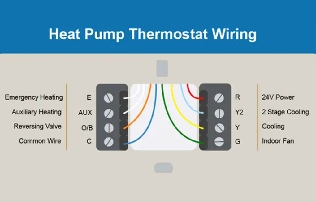
The heat pump wiring diagram shows the wiring colors to attach to each terminal. This is the most common wiring setup for a standard heat pump.
Below is a list of wire colors and what they are used for in standard thermostat wiring for heat pumps. No, the colors aren’t crucial – all the wires inside the colored housings are the same.
But using a standardized list of wiring colors for each task the thermostat performs gives technicians and future users the same information to work with.
Y – Yellow: Cooling – this wire energizes the control for the condensing unit, the outdoor unit. If your heat pump is a 2 stage unit, then your thermostat will also have a Y2 terminal for the second heating/cooling stage.
G – Green: Fan – this is for the blower in the air handler.
R – Red: 24 Volt Power – converted to 24V for the thermostat.
C – Blue: Common wire for continuous 24 volt power from the thermostat to the air handler.
E – White (optional): Emergency Heat. Most heat pump air handlers have an electric heating strip or strips in them (5kW to 20kW) to provide extra heat when the heat pump isn’t providing any during mechanical failure. If your air handler doesn’t have heating strips, you won’t have this wire or you won’t need to use the white wire or wires.
Aux – White (optional): Auxiliary Heat. This powers heating strips too, if your air handler has them.
But Aux is used in two scenarios. First, when the heat pump is working but can’t keep up with extreme cold temperatures, the heating strips are energized to provide supplemental heat. Secondly, Aux is powered when extra heat is needed immediately, for example, if the thermostat setting is increased significantly, such as from 72F to 76F.
O/B – Orange or Dark Blue: If orange, the Reversing Valve is powered in Cool mode. The reversing valve is the valve that changes the direction of refrigerant flow, so that your system can switch from Cool to Heat mode.
If dark blue, the thermostat is for one of the minority of heat pumps like the Reversing Valve in Heat mode.